All about wiring of electric motors EEP
The basic idea of an electric motor is really simple: you put electricity into it at one end and an axle (metal rod) rotates at the other end giving you the power to drive a machine of some kind. How does this work in practice? Exactly how do your convert electricity into movement?
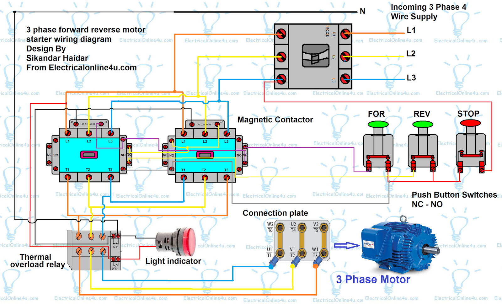
Forward Reverse Motor Control Diagram For 3 Phase Motor
Search hundreds of online and print manuals and get the right one from Haynes. Search hundreds of online and print manuals and get expert repair guidance from Haynes.

2 Speed Motor Wiring Diagram Sustainablened
Electrical symbols & electronic circuit symbols of schematic diagram - resistor, capacitor, inductor, relay, switch, wire, ground, diode, LED, transistor, power supply, antenna, lamp, logic gates,.

Labelled Diagram Of Electric Motor Nest Thermostat E Wiring 3 Wire To 4
A typical electric motor wiring diagram consists of various symbols and lines that represent the motor, power source, starting mechanism, control circuitry, and other components. These diagrams are designed to illustrate the flow of electricity and the connections between different parts of the motor.

3 Phase Motor Wiring Diagram Easy Wiring
DC motor that combines the series and the shunt motors. theory regarding the flow of flows from positive to negative. method of braking an AC motor (DC) is applied to the stationary after the AC voltage is removed. motor connection arrangement wired end to end to form a completely. motor made for two voltages.

Course Motor1 An Introduction to Electrical Motors Basics
HowStuffWorks To understand how an electric motor works, the key is to understand how the electromagnet works. (See How Electromagnets Work for complete details.) An electromagnet is the basis of an electric motor. Say that you created a simple electromagnet by wrapping 100 loops of wire around a nail and connecting it to a battery.
What Energy Transformation Takes Place In A Simple Electric Motor
Diagram & Working - ElectricalWorkbook What is an Electric Motor? Diagram & Working In this topic, you study Electric Motor - Diagram & Working. An electric motor is a machine which converts electrical enegy into mechanical energy and so its function is exactly the reverse of that of a generator.

3 phase motor connection motor control circuit electrician training
Electric motors and generators. Electric motors, generators, alternators and loudspeakers are explained using animations and schematics. This is a resource page from Physclips, a multi-level multimedia introduction to physics ( download the animations on this page ). Schematics and operation of different types of motor. DC motors.

wiring How to wire up a singlephase electric blower motor
How Electric Motor Works - 3 phase induction motor AC alternating current. 🎁 Sign up for a Free Trial at ️ https://greatcourses.thld.co/engineeringmindsetj.
Direct Online Starter Animation Diagrams Electrical Online 4u
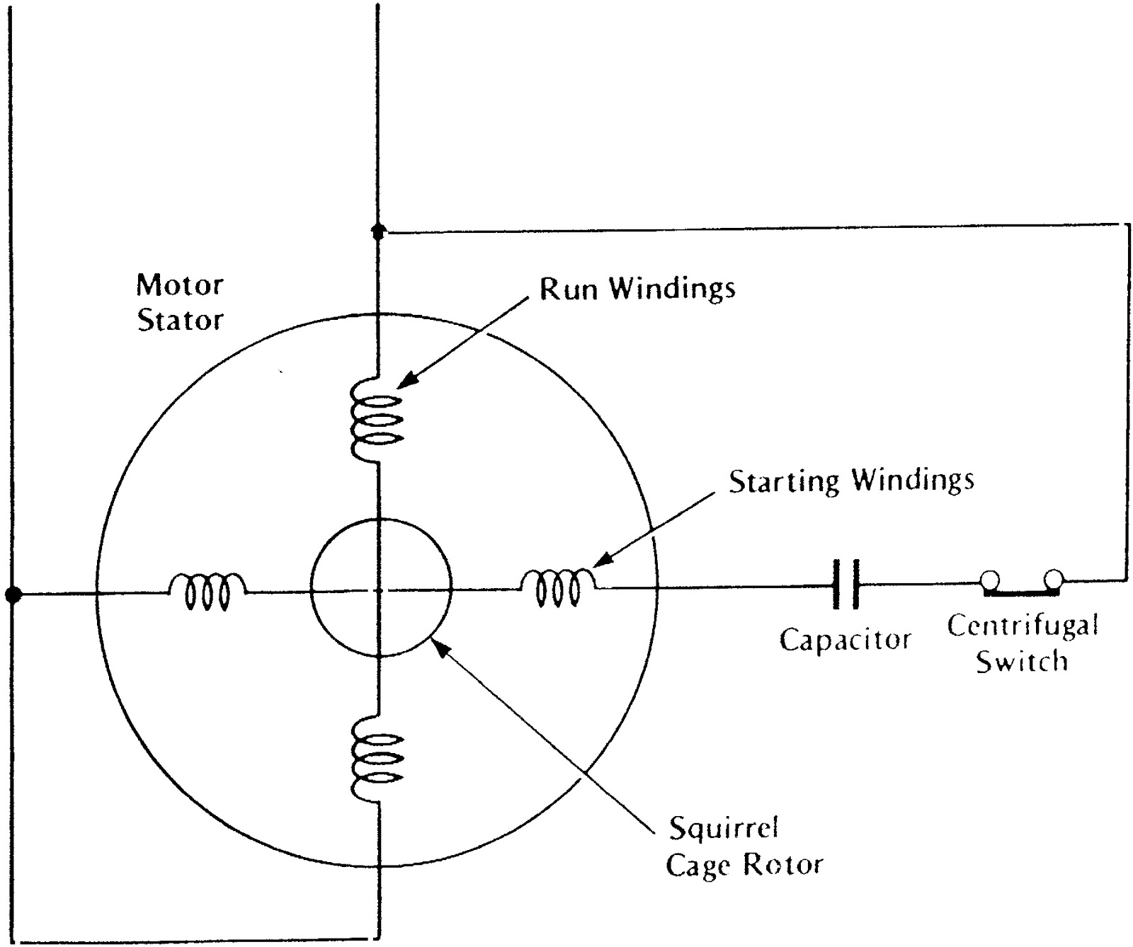
Universal Electric Motor Wiring Diagram. A Universal Electric Motor is designed to operate on alternating or direct currents (AC/DC). It is a series wound motor. It is provided with a field winding on the stator, connected in series with a commutating winding on the rotor.

Wiring Diagram For 3/4 Hp 120volt Reverseable Motor
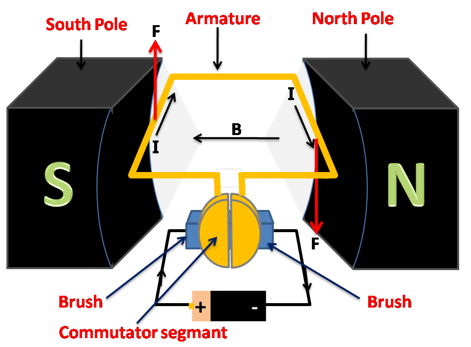
The first practical electric motor was invented by Thomas Davenport in 1834. This direct current (DC) motor utilized a stationary electromagnet as its stator to create a stationary magnetic field. The rotor, the motor's moving component, was also an electromagnet powered by current, transferred via a commutator and brushes.

Leeson Motor Wiring Diagram Free Wiring Diagram
The diagram shows a simple motor using direct current (dc). Fleming's left-hand rule can be used to explain why the coil turns Starting from the position shown in the diagram of the dc.
1 Phase Motor Wiring Diagram Artsist
The electric motor diagram is an essential tool for understanding the inner workings of an electric motor. This diagram provides a visual representation of the various components and their connections within the motor, helping to explain how it functions and how it can be controlled.
Explain the working of an electric motor with a neat diagram.
75 of the top 100 retailers can be found on eBay
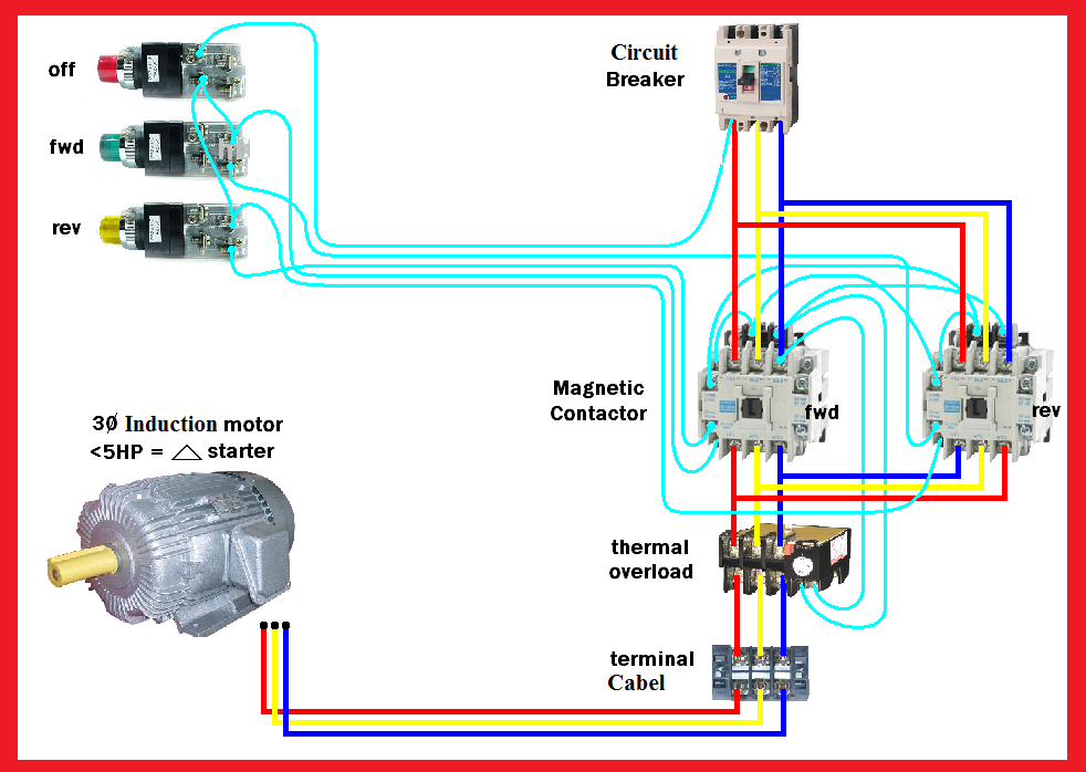
Motor Forward Reverse Wiring Diagram
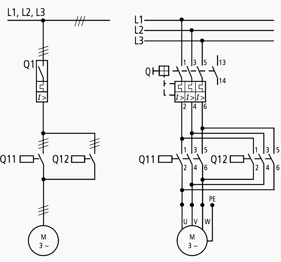
2.3 Terminal markings for electric motors 21 3. Starting and switching motors 23 3.1 Selection criteria overview 23 3.2 Selecting the right contactor for an application 24 3.3 Selecting the right overload for an application 24 3.4 Characteristic features of the commonly used starting methods for squirrel-cage induction motors 25 4. Diagram types 26
4 Wire Ac Motor Wiring Diagram
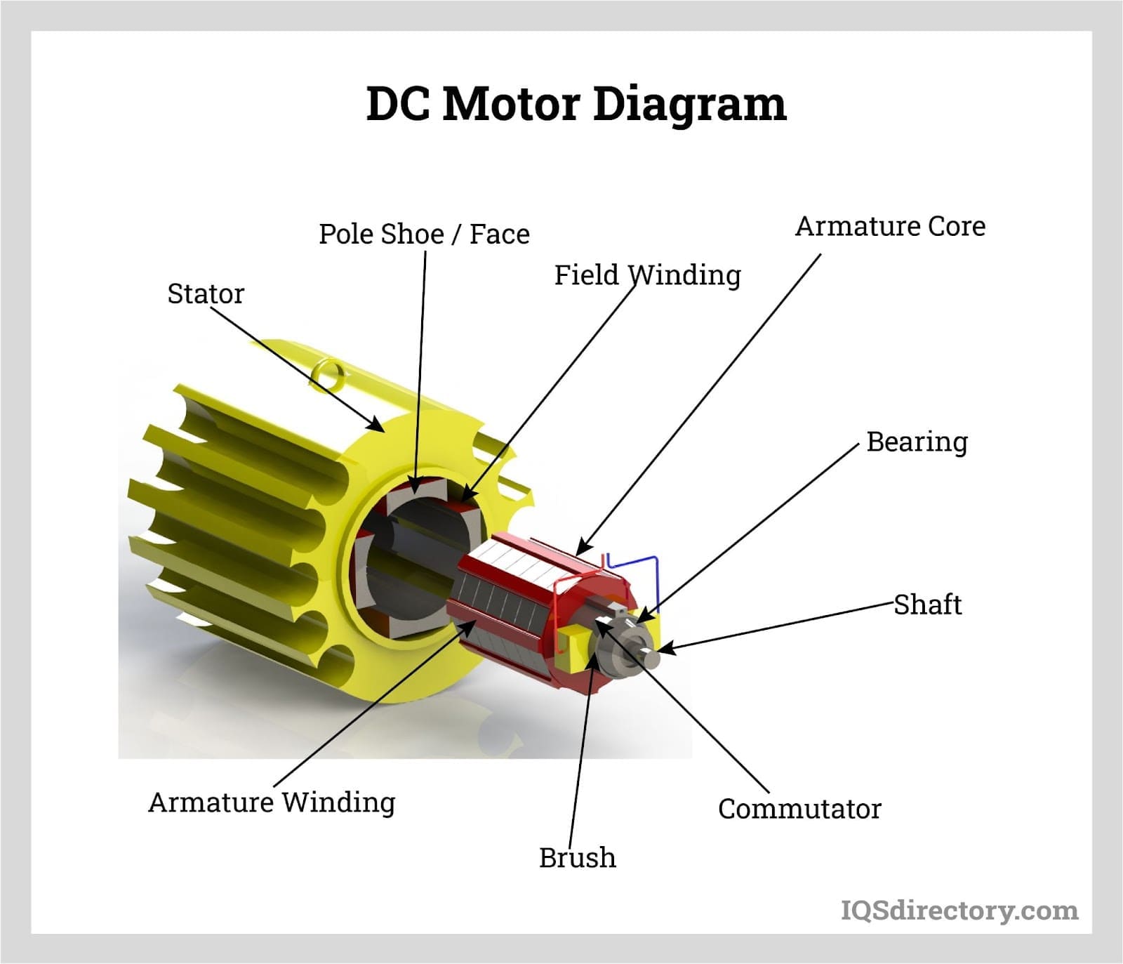
The schematic diagram of an electric motor typically includes components such as a rotor, stator, commutator, brushes, and a power supply. These components work together to generate rotational motion. The rotor is the rotating part of the motor, while the stator is the stationary part.